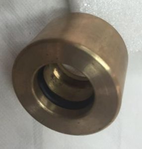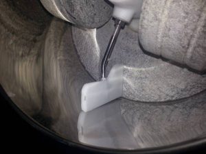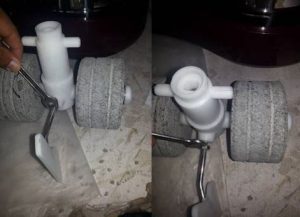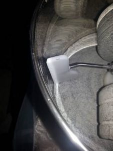
We stock and provide a full gamut of parts for all the models.
Parts of the most recent models are generally shipped within 24-48 hours of an order. Please contact us at [email protected], if you need anything that you do not find or to check availability.
Click here to view some common service procedures
 FAQs and Trouble shooting the spectra 11
 Instructions on installation/removal of bush bearings
 Instructions on changing the switch on spectra 11
 Leakage around central Shaft on Spectra 20 40 65 100 Models
 Installation of Castor Wheels on the Spectra melangers
 How to replace roller bushing
 Spectra 25/45/70/105/155 Exploded Parts List
 Control panel unidrive model drive
 Assembling and Disassembling the “Center shaft” in the Spectra 20, 45, 60 and 100 models
 Instructions on changing the fan on spectra 11
 Instructions on changing the belt on spectra 11
 Spectra 11 – Instructions to adjust gap between drum wall and scraper arm
 Spectra 11 – Instructions to change connector / scraper arm / roller stones
FAQs and Trouble shooting the spectra 11
In case you are facing any issues with the Spectra 11, as a first step, we recommend going through the following to see if it helps overcome the issues:
NOTE : Opening the unit does not preclude any warranty, and most of our customers are typically enthusiasts who can and usually do open the machines. Instructions to open the unit are on our webpage at http://www.spectraplaza.com/common-service/ . However, Use the services of a professional electrician or mechanic, or an authorized service personnel if you are not comfortable with it.
However, you must follow the general precautions below :
1) As with all electrical appliances, remove the connection to the wall socket.
2) Setup unit in a comfortable work area as the unit is heavy to work with.
3) Place a clean material (such as paper or cloth) on the work area to prevent scratches to the body of the unit.
4) Use the services of a professional electrician or mechanic, or an authorized service personnel if necessary.
5) Remove the heavy rollers stones and the drum unit aside so as to not drop on yourself.
6) Ensure that the machine has not been running and the motor is not hot, prior to opening up the unit.
FAQs and Troubleshooting Guide :
1) I am running the machine with the drum and rollers stones removed. Yet, the machine is noisier than usual.
- Hold the palm of your hand on the top of the dome and see if the noise reduces. If so, the dome may not be tightly screwed on and could be tightened. It is also possible that that ventillators on the body are loose.
2) The Bowl has stopped spinning though I hear the motor running?
- Remove the drum off the machine and note if the central vertical Stainless steel shaft is rotating. If not rotating, the belt is likely broken and may need to be replaced. Instruction to change the belt are on our website at www.Spectraplaza.com
- If the vertical SS shaft is rotating, then the central white cone fixed inside the drum to the stone base may be loose and not fixed permanently to the stone. This cone may be glued back on using any epoxy glue.
3) The Motor appears to be overheating and I feel the dome getting very hot?
- The motor fan may be broken and needs replacing. Or, the motor has become defective and needs to be replaced. In such cases, do not run the machine unattended and please contact us.
4) I connect the machine and it will not turn on?
- Ensure that the wall socket you connect to, has not tripped and any other appliance connected to the same wall socket works ok.
- Ensure that the proper voltage is applied to the machine – 110 volts versus 220 volts. This is generally applicable in only those countries where dual voltages are available.
- Ensure that the motor itself is not working. Sometimes, the motor may be working but the drum may not rotate, indicating a problem with the drum/belt, and not necessarily the motor.
- Ensure that the switch is engaged and functioning properly.
If all of the above have been reviewed, then only three possibilities exist :
a) The wire cord is faulty
b) The switch is faulty and
c) The motor is faulty
All of which can be easily replaced if we send in the parts, and you contact us.
5) The motor seems to have stopped working in the middle of a run?
The motor is equipped with a Thermal Overload Switch that will turn off motor if it gets too hot due to overload of contents or too thick materials, or voltage fluctuations. It will automatically restart after 20 to 30 minutes once motor cools down. In this case, you are requested to remove the food contents from the drum to reduce the load
6) The drum is rotating but the roller stones will not turn?
- Unscrew the two end nuts and remove the rollers of its axles. If there is any food material accumulated on the axles or within the roller axle sleeves, clean and assemble back.
- Check the roller axle sleeves for any damages or cracks.
- If the rollers would turn on empty but not when food material is added, check that the food is not jammed under the rollers. Typically, smaller sized food particles of about 5 mm or less should be added, and the addition should in small quantities at a time, and not added in bulk into the drum. Always start the machine empty and add the materials gradually and in small quantities.
7) I dropped or hit the roller stones and the edge of the roller stone has chipped? Can I use it?
Typically, if the roller edge has chipped and is rough, it may lead to further breakage and passing of stone pieces into the food. Though it may not affect the grinding performance or efficiency itself and can continue to the used as usual. Therefore, we suggest changing the roller stones or alternatively, grinding down the chipped area into a smooth surface so that further pieces do not break off at the chipped area.
8) The drum rotating appears wobbly and not level?
- This is ok and does not affect the performance in any way. It is only cosmetic.
9) The belt wore out fast and am having to replace often?
- Typically a belt should last for a year or more. If wearing out often, it may be that the motor pulley and the black plastic pulley are not level. Please write to us and we will send you the right pulleys and right instructions to level the two pulleys.
10) One or both rollers appear to turn slowly, or in fits and starts?
- Typically, it happens when the food material is very viscous and thick, and/or the amount of viscous food is high. Try reducing the quantity and where possible, the food material more free flowing.
- The roller axles may have dried up food accumulated on them and affect the spinning of the rollers, and needs to be cleaned every few days. (Please see the service page at www.Spectraplaza.com)
- Please see if the rollers are of the same size and measure atleast 109 mm or more in diameter.
- Place the connector on a flat surface and see if the axles are level on both sides
- Remove the rollers off the axles, clean the bushings within and ensure that the bushings are not broken or cracked.
Instructions on installation/removal of bush bearings
GENERAL PRECAUTIONS :
1. As with all electrical appliances, remove the connection to the wall socket.
2. Setup unit in a comfortable work area as the unit is heavy to work with.
3. Remove the heavy rollers stones and the drum unit aside.
4. Tools needed – wooden mallet/soft headed hammer, and a long blunt headed steel tool
INSTALLING THE BUSH BEARING
1. Place the bush bearing in the placeholder on the roller stone and gently tap with a wooden mallet or soft headed hammer, to force it into place.
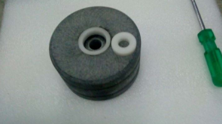
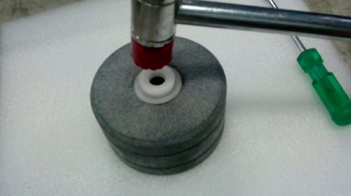
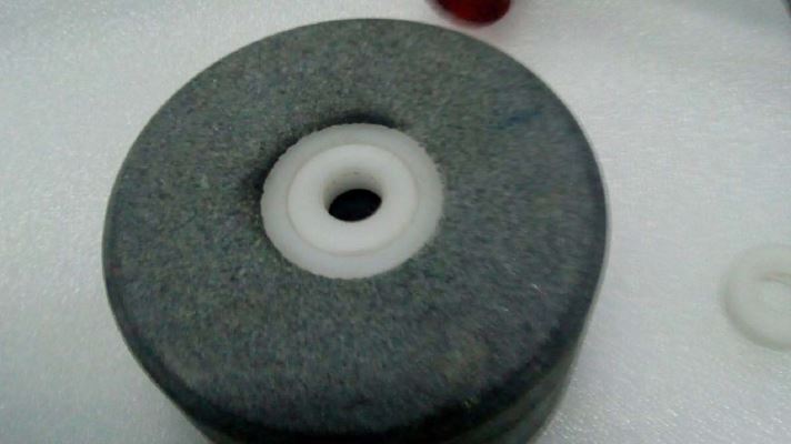
REMOVING THE BUSH BEARING
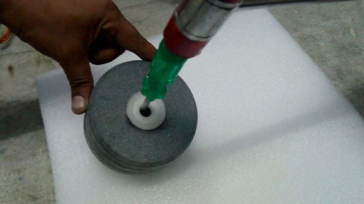
Gently push/tap the bearing out using a blunt nosed long tool from the opposite in-side as shown in the images.
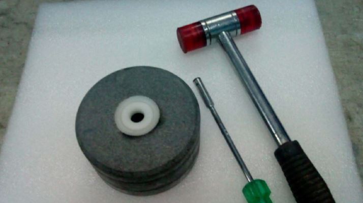
Instructions on changing the switch on spectra 11
GENERAL PRECAUTIONS :
1. As with all electrical appliances, remove the connection to the wall socket.
2. Setup unit in a comfortable work area as the unit is heavy to work with.
3. Place a clean material (such as paper or cloth) on the work area to prevent scratches to the body of the unit.
4. Use the services of a professional electrician or mechanic, or an authorized service personnel if necessary.
5. Remove the heavy rollers stones and the drum unit aside.
6. Ensure that the machine has not been running and the motor is not hot, prior to opening up the unit.
OPENING THE UNIT :
1. Place the unit upside down and remove the screws at the bottom of the unit.
2. Holding the top and bottom parts of the unit firmly, turn the unit over and place it on the work top in normal position.
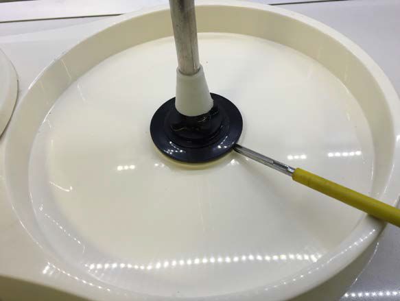
3. With a screw driver, gently pry the plastic lock around the spindle as shown in the picture below.
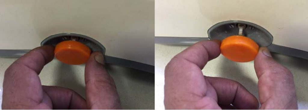
4. Gently tug on the Orange Switch knob and remove, and set it aside.
5. After the lock is removed and Orange switch knob is removed, turn the unit upside down, and remove the 8 recessed screws. Then, remove the top cover of the unit and set nearby on the work top, as shown in picture below. If you see some black dust inside the machine, that is normal as it is the wear and tear of the belt if it has been used for a few days or more. It may be vacuumed away or cleaned with a soft cloth.
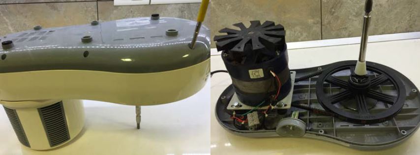
6. Gently lift the screw assembly. You can remove the switch module off the Switch assembly by unscrewing the two screws as shown in picture below.
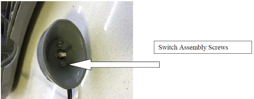
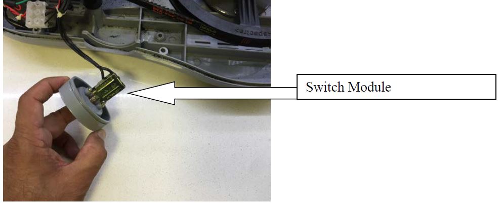
7. Remove the two lead wires from the Switch that connect into the Terminal as shown below.
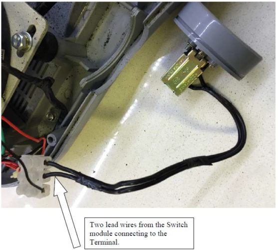
8. Replace the Switch Module with a new one, screw it back on to the Switch Assembly, connect the lead wires back to the Terminal. Place the top cover on the unit, and screw back on the screws at the bottom of the unit.
Leakage around the “Center shaft” in the Spectra 20, 40, 60 and 100 models
Leakage around the “Center shaft” in the Spectra 20, 40, 60 and 100 models :
In case of a leak around the Central Stainless Steel shaft on any of these models, the cause is often arrested by tightening the Lock Nut at the bottom of the machine.
Remove the rollers stones off the machine.
Disconnect the machine from electrical power supply entirely.
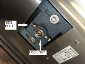
Simply loosen the two Side bolts, then, tighten fully the LOCK NUT, and then retighten the two Side bolts, that are shown in the image below.
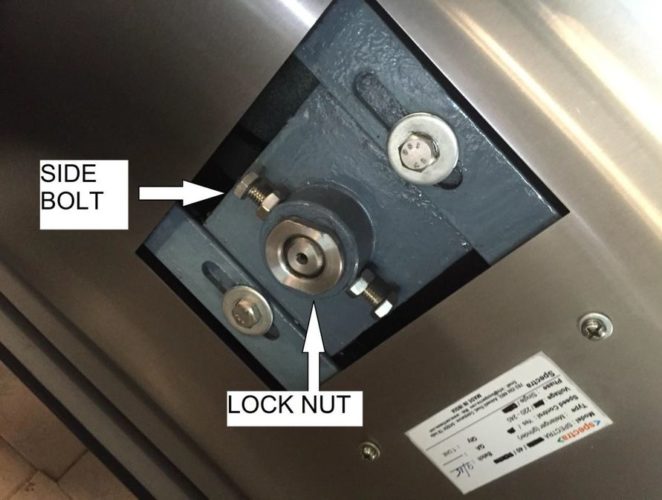
In case this does not arrest the fault, and the leak is only around the central shaft, then it may need disassembling and assembling back the central shaft and other components, which is a more involved process, and separate instructions are available for that.
Installation of Castor Wheels on the Spectra melangers
Installation of Castor Wheels on the Spectra melangers :
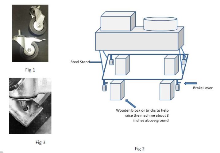
The Castor wheel (Fig 1) set is a set of 4 wheels for the Spectra melanger. It is provided to ease the movement of the heavy machine on any smooth floor. Two of the Four wheels have brake locks on them, which when engaged, prevents the machine from moving.
Installation:
1. Turn off the power and remove the electrical plug from the socket to avoid any electrical risk.
2. Remove the roller wheels and set aside to reduce the weight of the machine.
3. Take 4 equal blocks of wood/brick or similar item which is at least 8 inches or more in height.
4. Set them apart and then, lift the Spectra melanger and place it on the blocks, such that the steel stand of the Spectra melanger is above the floor, and resting on the wooden/brick blocks (Fig 2).
5. Install the 2 castor wheels with brakes on the front side of the Spectra melanger, and the 2 castor wheels without the brakes may be installed on the rear side of the melanger. (Fig 2).
6. While installing, simply screw in the castor wheels into the receiving threaded hole at the bottom of the stand, as shown in the Figure (Fig 3).
7. Tighten fully by hand, by rotating the castor wheel assembly.
8. Place the machine back on the floor by carefully removing the blocks.
To Use:
1. Release the Brake locks by keeping the Lever in the “UP” position.
2. Move the machine to your desired location on the floor.
3. Lock the wheels by pushing the Lever to the “Down” Position.
How to replace roller bushing
Instructions :
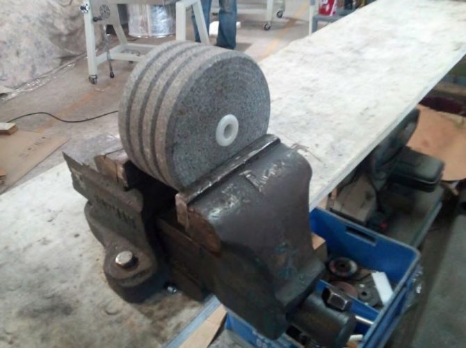
In the Spectra melangers, the roller bushes will wear out after a year or two, and is normal. We recommend replacing it every two years or sooner, and where not possible to replace, you may replace the entire rollers as a pair.
The basic concept is the same for all the models. We are introducing in the near future a newer type of bushing where it is very easy to replace the bushing without any tools or machine shop access .. Until then, the the following is the procedure to replace bushing.
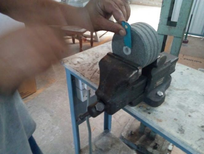
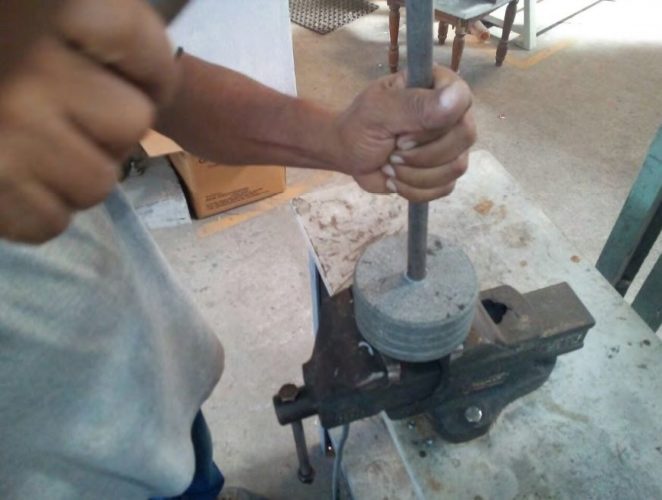
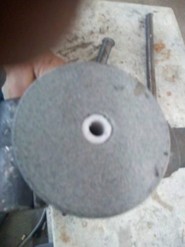
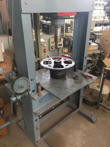
We normally use hydraulic presses like in Picture 9 to remove and to press a bushing. However, if such a facility is not available, then, one can use a hammer to remove and press in a bushing, as shown in images 1 through 8 (or a reamer on a lathe to take it out). Also, a chisel and rod may be used to remove the bush head from the old roller if needed (as shown in pic 2).
If the bushing is slightly larger to fit the hole in the stone rollers, it may be gently filed or (reduced on a lathe) for a tight and perfect fit.
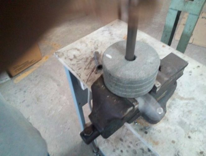
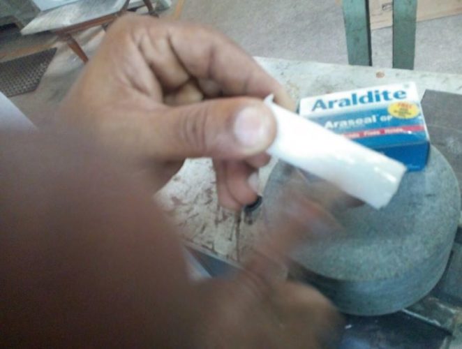
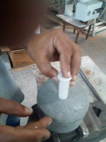
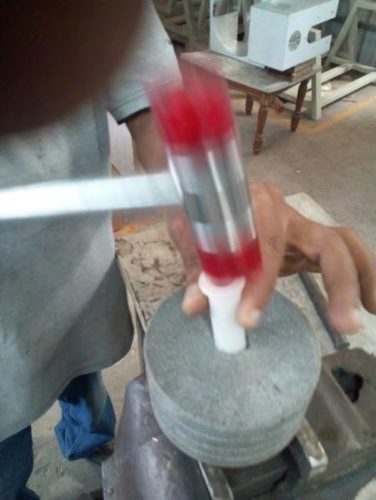
Spectra 25/45/70/105/155 Exploded Parts List

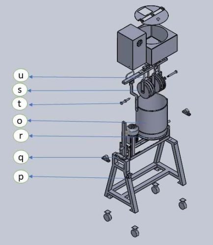
a) Lid
b) SS Body
c) Top Nut
d) Spring
e) Spring Plate
f) Suspenders with gun metal bush
g) Forks
h) Stone Rollers with bush bearing
i) Axles
j) Bed
k) Flange
l) Flange Bush
m) A Frame
n) Castor Wheels
o) Drum
p) Tilt Lock set
q) Lock Set
r) Chain with sprocket
s) Scrapper arm
t) Axle washers
U) Top Bar
v) Motor with sprocket
Focus View

CONTROL PANEL UNIDRIVE MODEL DRIVE
DIAGNOSTICS
The keypad display on the drive gives various information about the status of the drive. The keypad display provides information on the following categories:
- Trip indications
- Alarm indications
- Status indications
Status modes (Keypad and LED status)
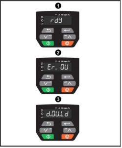 1. Drive OK Status
2. Trip Status
3. Alarm Status
Trip indications
The output of the drive is disabled under any trip condition so that the drive stops controlling the motor. If the motor is running when the trip occurs it will coast to a stop.
During a trip condition, the display indicates that a trip has occurred and the keypad will display the trip string. Some trips have a sub-trip number to provide additional information about the trip. If a trip has a sub-trip number, the sub-trip number is flashed alternately with the trip string.
Trips are listed below. The most recent trip can be read in Pr. 10.020 providing a trip number.
Step 1 : OI.AC – Instantaneous output over current detected
The instantaneous drive output current has exceeded VM_DRIVE_CURRENT_MAX
Recommended actions/checks:
- Increase acceleration (Pr 00.003) /deceleration (Pr 00.004) rate.
- Check for short circuit on the output cabling in drive side by disconnecting the motor.

- Check integrity of the motor insulation


Step 2 : OI.SC – Output phase short-circuit
Over-current detected on drive output when enabled. Possible motor earth fault.
Recommended actions/checks:
- Check for short circuit on the output cabling in drive side by disconnecting the motor.

- Check integrity of the motor insulation


Step 3 : OV – Over Voltage
DC bus voltage has exceeded the peak value or maximum continuous level for 15 seconds
Recommended actions/checks :
- Increase deceleration ramp. (Pr 00.004).
- Check nominal AC supply level
Check the voltage between L1 & L2-N terminal.

- Check for supply disturbance which could cause the DC bus to rise.
- Check integrity of the motor insulation


Assembling and Disassembling the “Center shaft” in the Spectra 20, 40, 60 and 100 models
Step 1 : The parts that go into assembling the central shaft are
a) Bottom Bush (Stainless Steel)
b) “O” Ring
c) Gun Metal bush
d) Oil Seal
e) Teflon Seal
f) Stainless steel center shaft
These parts are shown in the picture below.

Step 2 : The method of assembling is as follows
a) The Bottom bush is first glued on to the granite stone bottom with an epoxy glue and is permanently fixed at the factory.
b) Next the “O” ring is inserted into the Bottom bush. There will be two grooves within the gun metal bush. The narrower of the two accepts the "O" Ring. The wider of the two grooves is filled with white grease.
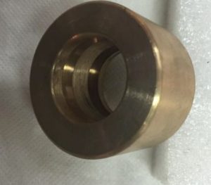 Gun Metal Bush showing the Grooves
C) The Teflon Washer, the oil Seal and the Gun Metal bush are slipped over the SS Shaft as shown below.
d) Then, the gear sprocket wheel is bolted using the four bolts to the bottom of the stone. The four bolts are not fully tighted at this stage.

e) Then, the Stainless Steel Central shaft is inserted from the top (ie. from inside the drum), through the Stainless Steel bush, and then and using a wooden hammer, hammered down as far as it would go, and through the gear sprocket bearings. If you have access to a Hydraulic Press in a machine shop of suitable size, then it could be used instead of wooden hammering.
The final assembly would appear as shown in picture above.
f) Finally, the entire assembly of the drum,stone and pulley is bolted down to the frame/chasis of the melangeur/grinder as below. The Lock NUT is first fully tightened, and then, the two side bolts are tightened.
Step 3 : To disassemble the central shaft, it is the reverse process.
a) Loosen the side bolts, and remove the Lock Nut.
b) With a wooden hammer, hit the central stainless steel shaft from bottom, such that the shaft moves up and eventually is removed from the unit.
Now, using a screwdriver or similar instrument, gently pry the Teflon seal, Oil Seal, Gun Metal bush and the ‘O’ ring out of the Bottom bush. In case of difficulty in prying out, you could nudge out the O Ring by pushing it out from the underside of the Bottom bush.
Instructions on changing the fan on spectra 11
GENERAL PRECAUTIONS :
1. As with all electrical appliances, remove the connection to the wall socket.
2. Setup unit in a comfortable work area as the unit is heavy to work with.
3. Place a clean material (such as paper or cloth) on the work area to prevent scratches to the body of the unit.
4. Use the services of a professional electrician or mechanic, or an authorized service personnel if necessary.
5. Remove the heavy rollers stones and the drum unit aside.
6. Ensure that the machine has not been running and the motor is not hot, prior to opening up the unit.
OPENING THE UNIT :
1. With a screw driver, gently pry the plastic lock around the spindle as shown in the picture below.
2. Place the unit upside down and remove the screws at the bottom of the unit.
3. Holding the top and bottom parts of the unit firmly, turn the unit over and place it on the work top in normal position.
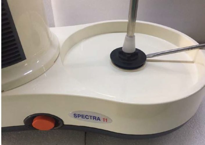
4. After the lock is removed, remove the top cover (plastic body) of the unit and set nearby on the work top, so as to expose the internals, as shown in picture below.
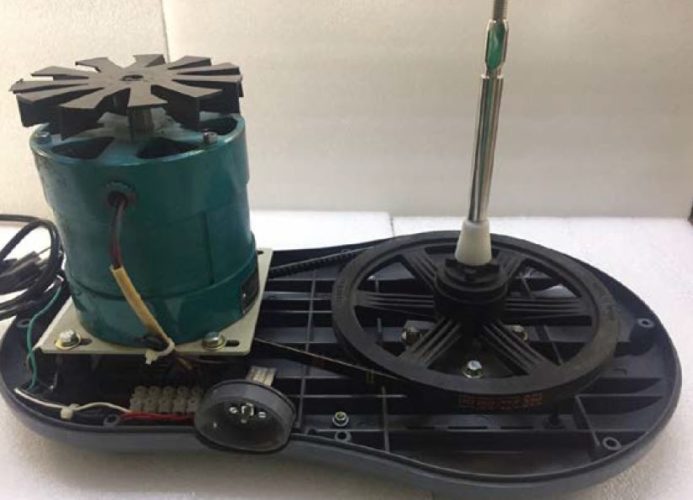
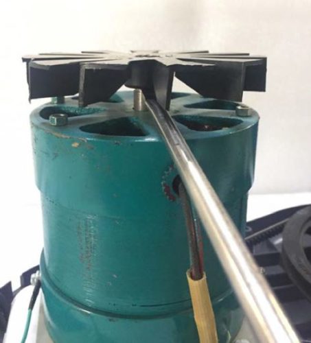
5. Using two screwdrivers, gently pry away the motor fan from the motor shaft as show below.
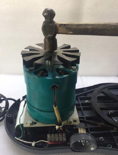
7. After removing the fan, install a new fan, ensuring the blades point downwards, by gently tapping with a small hammer on the fan.
8. Replace the top cover and screw back on the screws at the bottom of the unit.
9. Replace the plastic lock around the spindle by pressing it down.
Instructions on changing the belt on spectra 11
GENERAL PRECAUTIONS :
1. As with all electrical appliances, remove the connection to the wall socket.
2. Setup unit in a comfortable work area as the unit is heavy to work with.
3. Place a clean material (such as paper or cloth) on the work area to prevent scratches to the body of the unit.
4. Use the services of a professional electrician or mechanic, or an authorized service personnel if necessary.
5. Remove the heavy rollers stones and the drum unit aside.
6. Ensure that the machine has not been running and the motor is not hot, prior to opening up the unit.
OPENING THE UNIT :
1. With a screw driver, gently pry the plastic lock around the spindle as shown in the picture below.
2. Place the unit upside down and remove the 8 screws at the bottom of the unit.
3. Holding the top and bottom parts of the unit firmly, turn the unit over and place it on the work top in normal position.

4. Lift up the top cover of the unit (plastic body) and set nearby on the work top, thus exposing the internals of the machine, as shown in picture below.
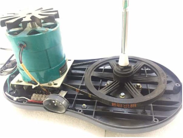
5. Using a screwdriver or a spanner, gently pry away the belt from the pulley as shown below. Remove the old belt by turning the large black pully and simultaneously using a screw drive to pry of the belt of the large black pully even while turning the pulley.
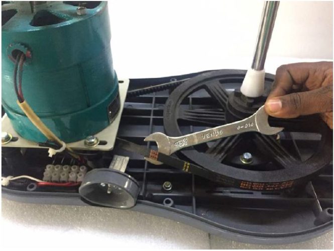
6. To fix a new belt
- Ensure that the belt sits in the small 1 inch pulley on the motor shaft.
- Take the rest of the belt and loop it on the larger black inch pulley.
- You will find it difficult to get the last few inches of the belt on to the pulley... At that stage, just rotate the drum black pulley and the belt will fall into place.
7. Replace the top cover and screw back on the screws at the bottom of the unit.
8. Push back the plastic lock back into position.
Instructions for Increasing Gap between Drum and Scraper Arm
Step 1 : GENERAL PRECAUTIONS
- As with all electrical appliances, remove the connection to the wall socket.
- Setup unit in a comfortable work area as the unit is heavy to work with.
- Place a clean material (such as paper or cloth) on the work area to prevent scratches to the body of the unit.
- Use the services of a professional electrician or mechanic, or an authorized service personnel if necessary.
- Remove the heavy rollers stones and the drum unit aside.
- Ensure that the machine has not been running and the motor is not hot, prior to opening up the unit.
Instructions for changing / replacing connector / rollestone / scraper arm
Step 1 : GENERAL PRECAUTIONS
- As with all electrical appliances, remove the connection to the wall socket.
- Setup unit in a comfortable work area as the unit is heavy to work with.
- Place a clean material (such as paper or cloth) on the work area to prevent scratches to the body of the unit.
- Use the services of a professional electrician or mechanic, or an authorized service personnel if necessary.
- Remove the heavy rollers stones and the drum unit aside.
- Ensure that the machine has not been running and the motor is not hot, prior to opening up the unit.
Step 2 : DISASSEMBLY
- Remove the rollers stones set out of the drum, and place on a firm surface.
- Using a wrench, unscrew the two nuts (flat plates) on either side of the stone rollers.
- Remove the stone rollers off the stainless steel shafts and set aside.
- Using a smaller spanner, loosen the lock nut in the Scrapper arm (T shaped steel and plastic arm).
- Twist the Scrapper arm and remove it complete from the Plastic connector.
Step 3 : ASSEMBLY
- Twist the Scraper arm back into the connector. Place the connector inside the drum and ensure that.
- The Scraper arm does not touch the wall of the drum nor the stone bottom. You can turn the scraper arm.
- And make it either move in or out. Also, ensure that the plastic part of the Scraper arm is vertical.
- Once correctly positioned, tighten the lock nut on the scraper arm.
- Replace the stones and tighten the two nuts (flat plates) on either side of the stone rollers.

